07/22/2020
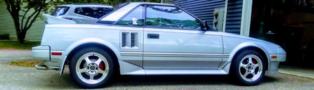
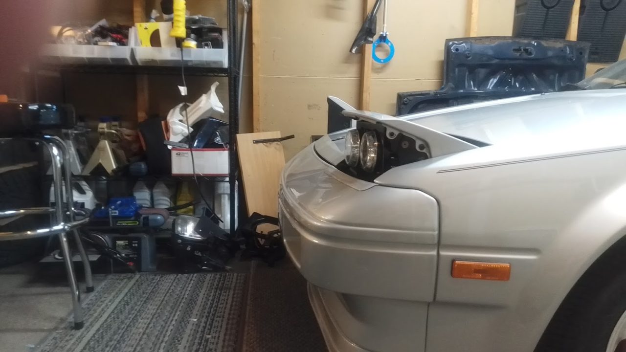
For many years now I have wanted low profile headlights. I also wanted to mimic the Lotus Esprit dual light design. Well, I finally got off my lazy butt and took the plunge. But, before we begin, know I bought a couple spare headlight assemblies from Neil Jones so I could go back to stock if I ever wanted to. Be warned, this is going to be long!
Items I purchased:
2 x headlight assemblies from Neil Jones (excluding the headlight motors, painted covers, plastics, bulbs, and chrome beauty rings)
2 x 24×6 inch 16 gauge steel plates from local hardware store (for main mounting structure and thickness required by Hella for their mounting clips)
2 x 24×6 inch 22 gauge steel plates from local hardware store (for possible covering to hide the mounting points and headlight adjustment points)
2 x Hella 008193027 – HELLA 008193027 90mm DE Series 12V Low Beam Halogen Headlamp Module
2 x Hella 008191057 – HELLA 008191057 90mm 12V High Beam Halogen Headlamp Module
***These seem to be out of stock but leaving link for visual*** 4pcs DC 12V H9 Female Adapter Wire Harness Sockets for Car Headlight Fog Light
https://www.amazon.com/gp/product/B07RPWXBGB/ref=ppx_yo_dt_b_asin_title_o03_s00?ie=UTF8&psc=1
2 x Plastic Male H4 (9003) Headlight Plug w/ 14ga Pigtail Wires fits 7” Round Lamps – https://www.hipoparts.com/plastic-male-h4-9003-headlight-plug-w-14ga-pigtail-wires-fits-7-round-lamps/
2 x J.W. Winco 6NXF2/A DIN71802 Ball Joint, 10 mm Diameter, M6 x 1.0 Tapped Right Hand Thread, M6 x 1.0 Threaded Shank, 12.5 mm Thread Length
https://www.amazon.com/gp/product/B019DNDQUK/ref=ppx_od_dt_b_asin_title_s00?ie=UTF8&psc=1
1 x Ace Hardware Plastic Pads 55928 https://www.acehardware.com/departments/home-and-decor/cabinet-and-furniture-hardware/protective-furniture-pads/55928
2 x M6 x 1.0 45mm phillips Head bolt (Combined with the Plastic Pads these will be for the bump stops)
12 x M6 x 1.0 Nyloc nuts (Metal nuts with nylon at top of threads preventing not from backing off of bolt but I don’t think I used them all)
8 x M5 x 0.80 16mm Allen dome head bolts in flat black (these combined with the M5 Nyloc nuts will hold the front plate to the side plates)
8 x M5 x 0.80 Nyloc nuts (Metal nuts with nylon at top of threads preventing not from backing off of bolt)
8 x M6 x 1.0 16mm Allen dome head bolts in flat black (these combined with the M6 Nyloc nuts will hold the side plates onto the headlight housing)
Tools purchased:
Metric step drill bits for the 10mm Hella mounting holes (for perfect round holes)
95mm hole saw (local hardware store “Menards” had in stock)
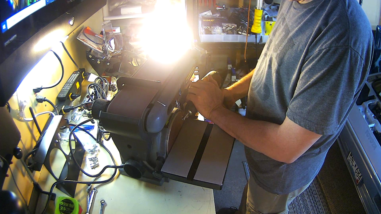
Bench sander with 6″ disc and long belt sanding area
Metal break (I bought the cheapest one at Harbor Freight and should have got a better one)
Drill press (make things easier and I wanted one anyway)
Now on to some warnings. I have never done this type of metal work before, bending metal, drilling large holes with a hole saw, and custom fab work. I used pressed cardboard for my templates and have learned a bit since.
My first attempt was to make a bolt in housing that fastened to the headlight assembly at the top and bottom in place of where the light bulb housing bucket once was. I learned the hard way that I wasn’t going to be able to get the Hella light housing high enough because of the cross bar at the top / front of the headlight assembly. Even after I used some nylon washers as spacers I just couldn’t get things lined up how I wanted. Things were close but not good enough.


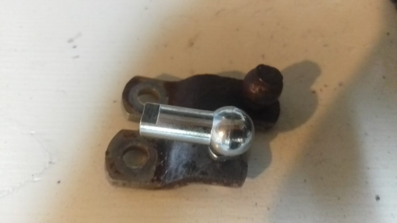
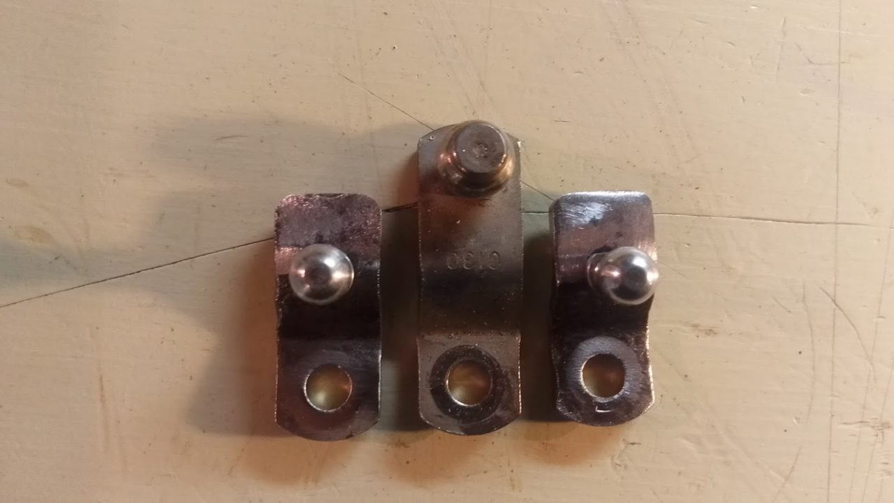
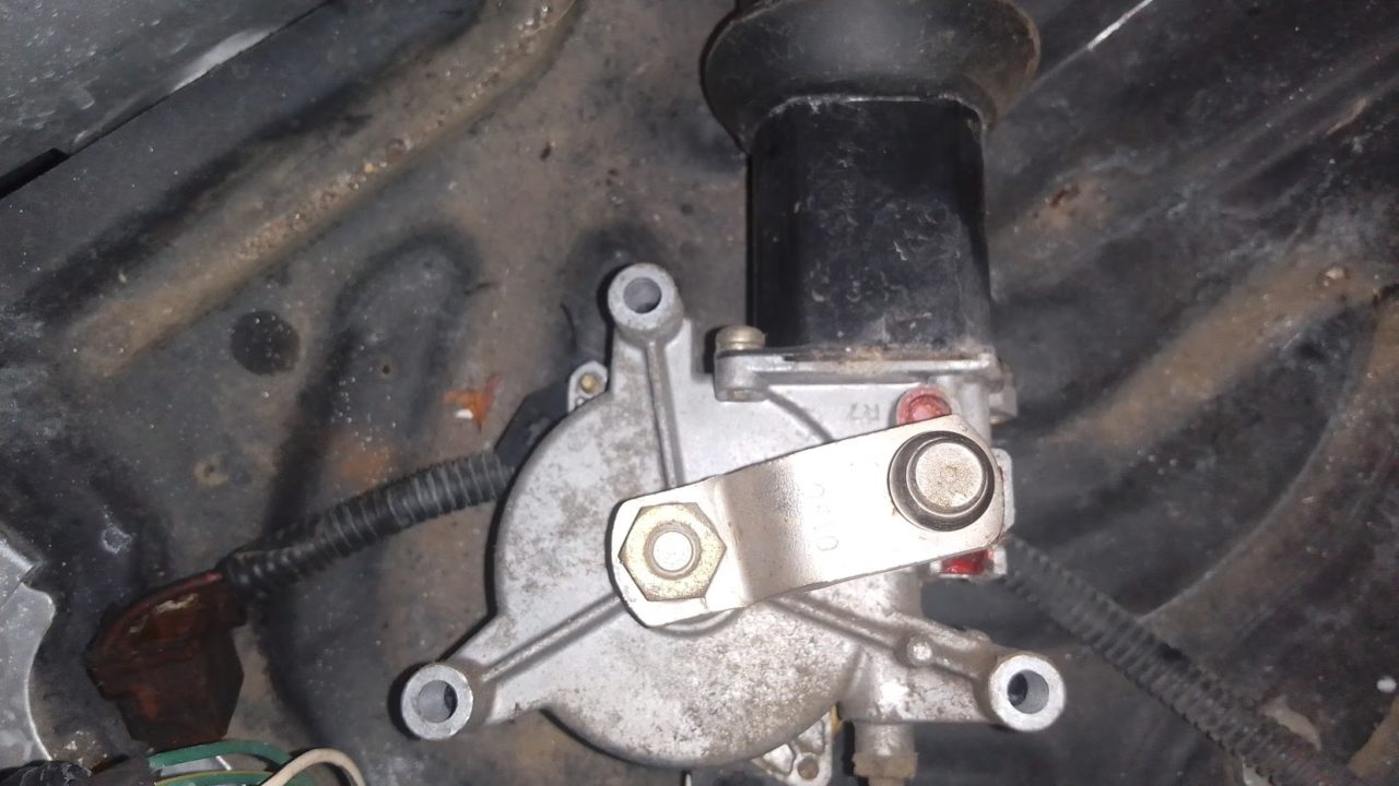
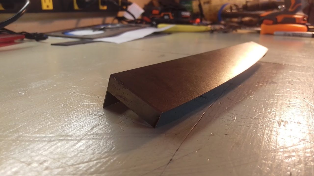
I also didn’t get the pivot arm changed to the correct position. Neil Jones once again to the rescue. As you can see, I didn’t move the ball joint close enough to the bend area. With the ball joint in this position, the lowest I could get the headlight was down to about 5 1/4 inches measured from the top of the eye lid to the bottom of the painted headlight cover. The factory height is about 7 1/2 inches measured in the same locations. My goal was 4 1/2 to 4 inches.
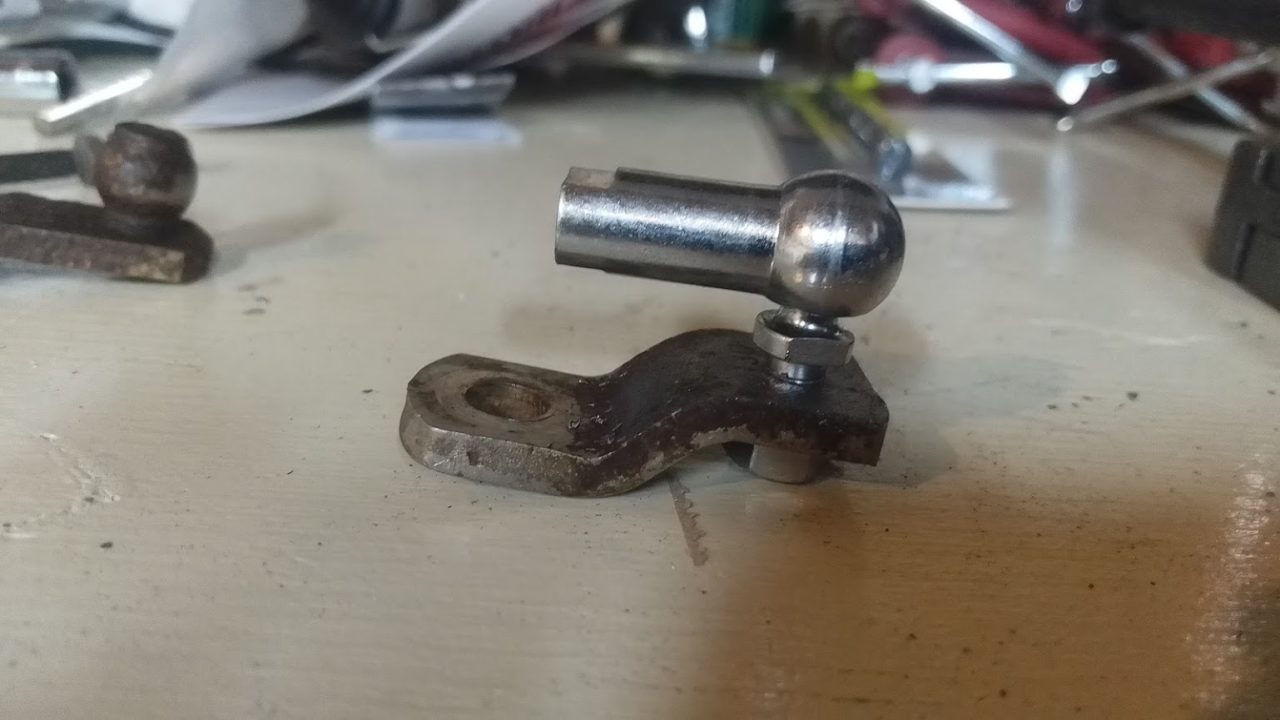

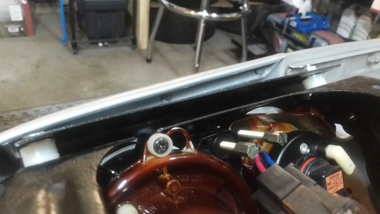
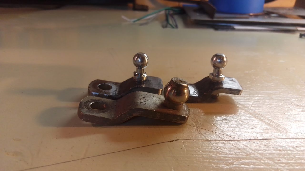
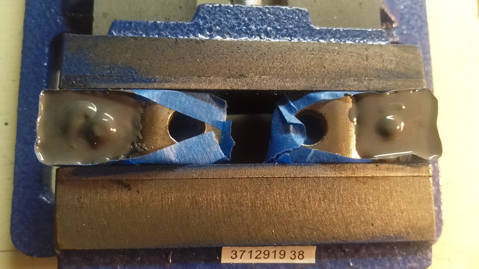
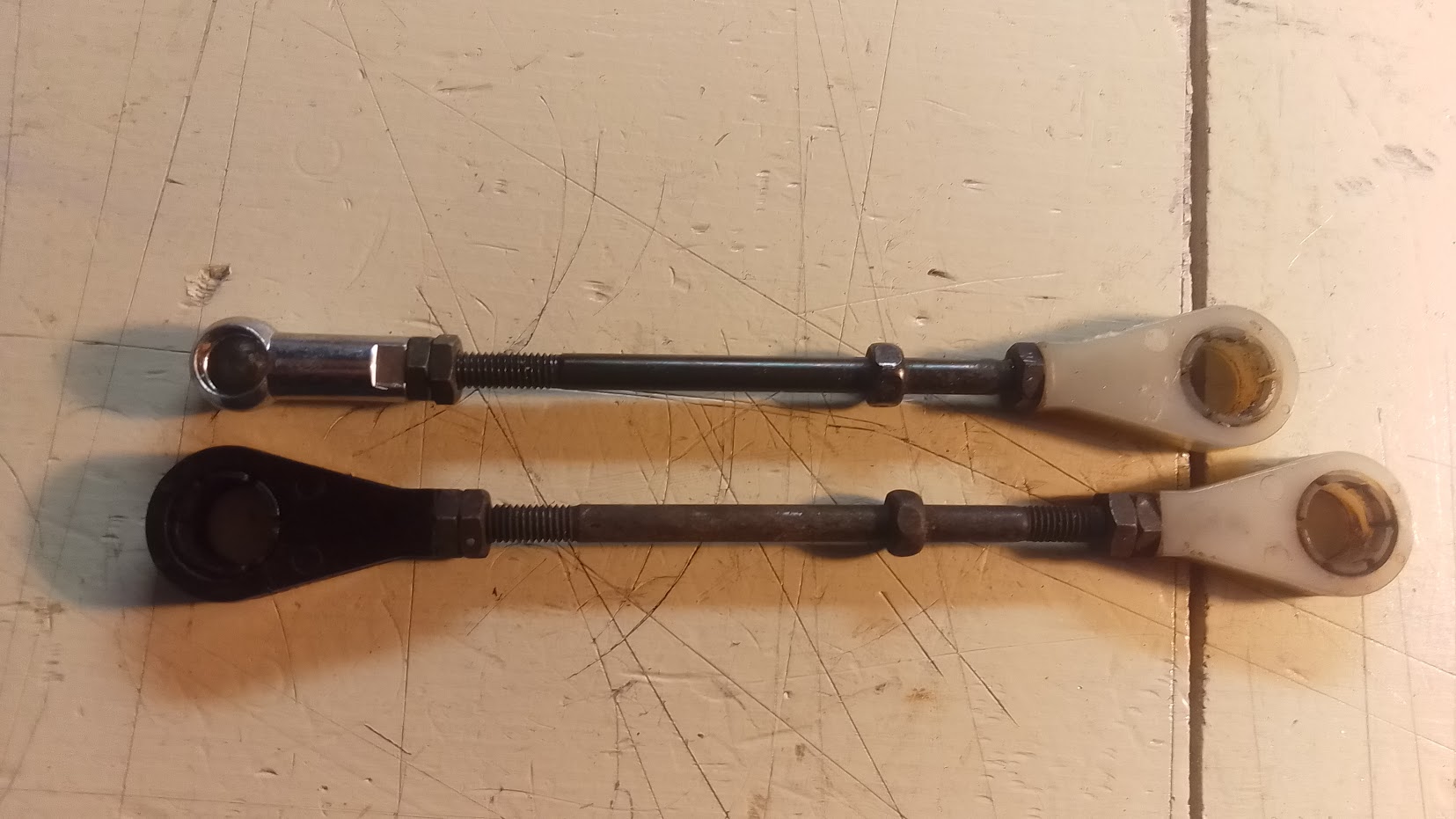
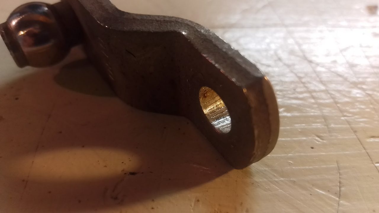
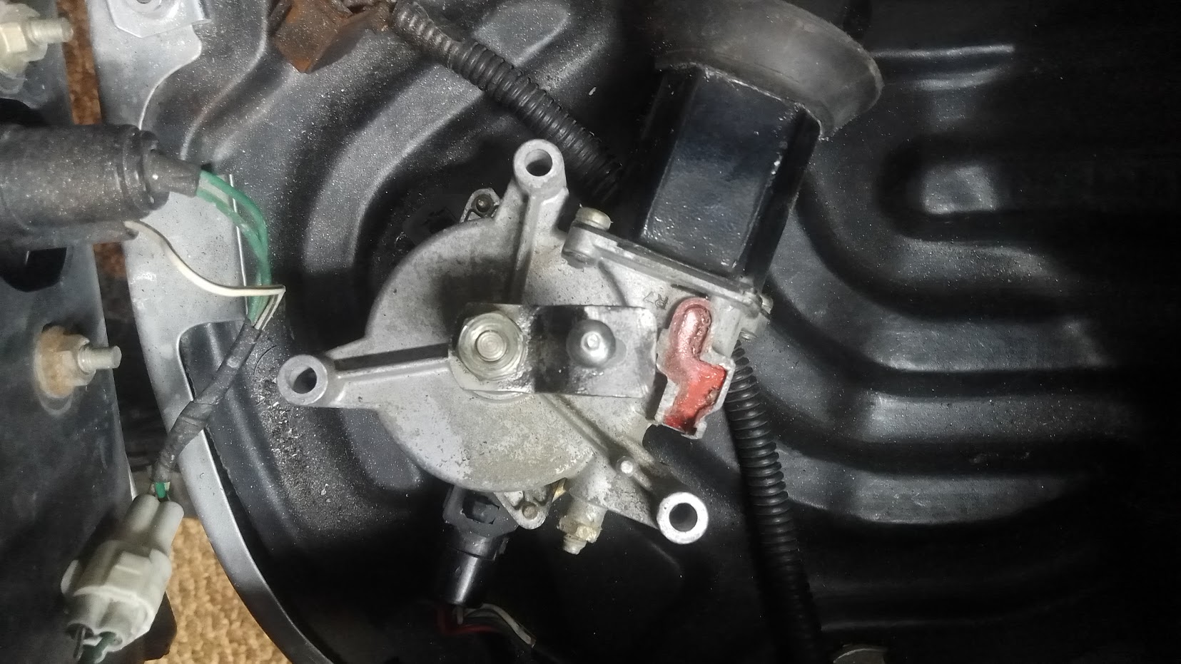
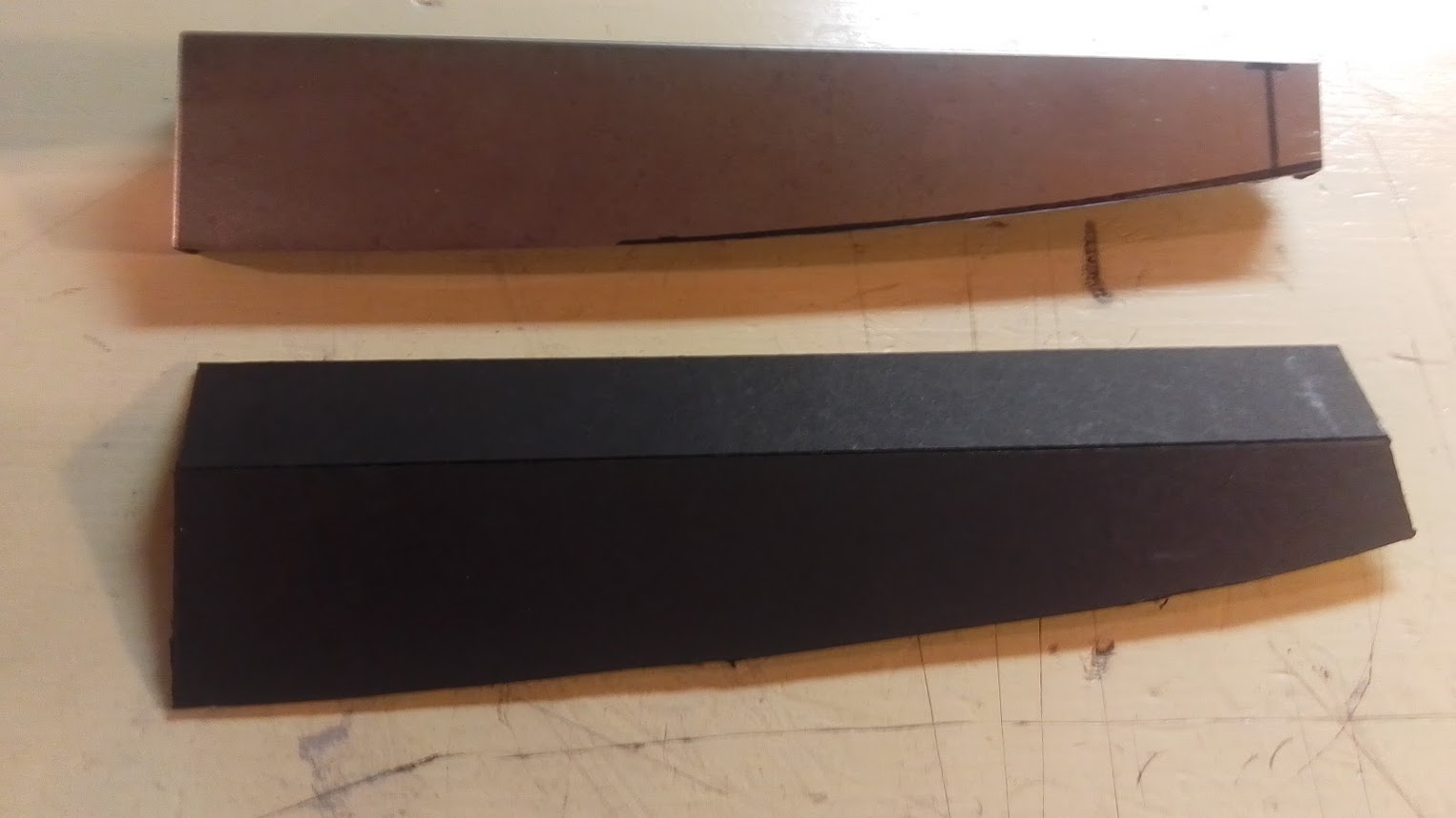
Pictures of the properly shortened pivot arms also compared to the factory length. Now I have them right where I need them. Also, since the hole is so close to the bend I couldn’t place the nut on the back. I did tap the hole to M6x1.0 and threaded the ball joints into the arms but wanted to make sure they were secure. I ended up J.B. Welding them. I don’t have a welder but if you do, welding them on would be even better. Either way, this should hold fine as the ball joints are already tightened into the threads I made. The J.B. Weld is just to make sure they stay put.
Some may think that just shortening the push rods would resolve this issue. Well, it won’t. See the pivot arm spins 360 degrees in one direction. The shorter the rod, the further down the headlight assembly must go. Changing where the arms ball joint is is the only way to get the assembly lowered as desired. Yes, the rod does need to be shortened as well but only to work WITH the ball joint repositioning.
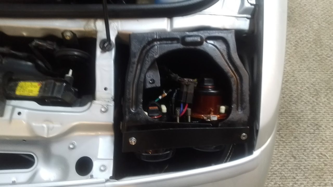
A last word of warning, until I can remember something else, I chose to unbolt the headlight motor off of the assembly and leave it in the car and plugged in. Battery was disconnected anyway but doing this made getting the headlight assembly out much easier. I also took a picture of where the pivot arm was while in the up position. The pivot arm hole that attaches to the motor has splines and needs to be lined up in a specific position or things won’t go up and down as factory. Watch the video below that shows how the assembly goes down a bit before going up, and goes up higher just before going down. Seems the person got the arm a spline or two off. Not my car but is the inspiration for me.
Wiring harness:
Since I wanted to be able to go back to the factory headlight assemblies I decided to make a small harness to go from the factory H4 connection to the two H9 connections.
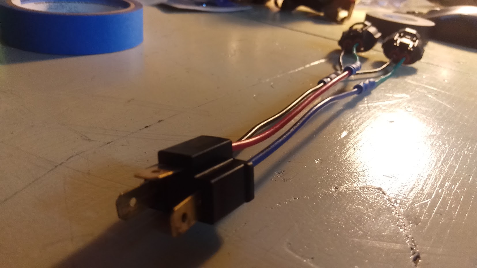
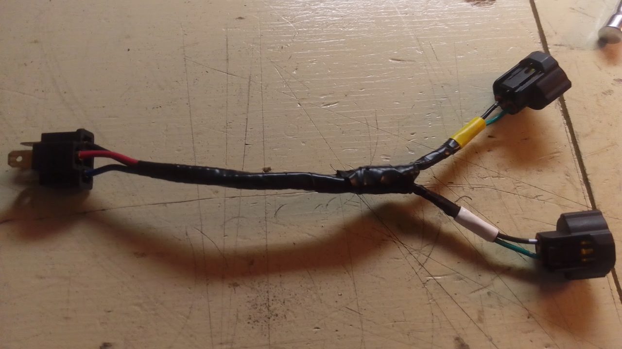
As you can see below, the red wire is for low beam, the blue wire is for high beam, and the black wire is for ground. Note the positions of the red and blue wires on the H4 plug. Just in case someone purchases a different brand H4 male connector and the wire color differs. I also used yellow electrical tape to signify the low beam and white electrical tape to signify the high beam after the wires were taped up for their protection.
Side note: From my understanding, as long as you pick the same side on the H9 connectors as the ground it doesn’t matter which side is the ground. I picked the black wires (left side) for simplicity sake.

Here’s a short video of the lights working but still in the wrong housing. See all that worthless space above the lights. Just terrible. I can do better.
Write-up section
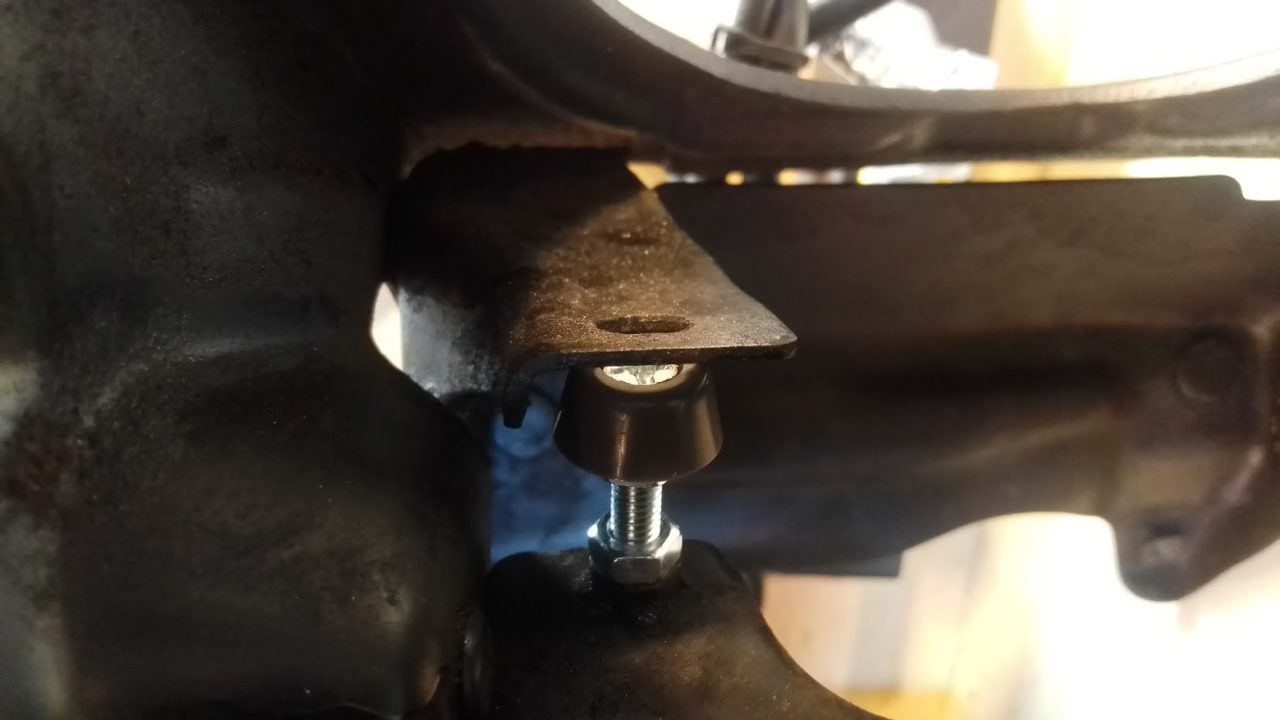
You’ve seen how I made the wiring harness. Now let me show you another important feature. The bump stop for the maximum height. If you don’t make this piece the headlights will bounce when going over bumps. Even little bumps.
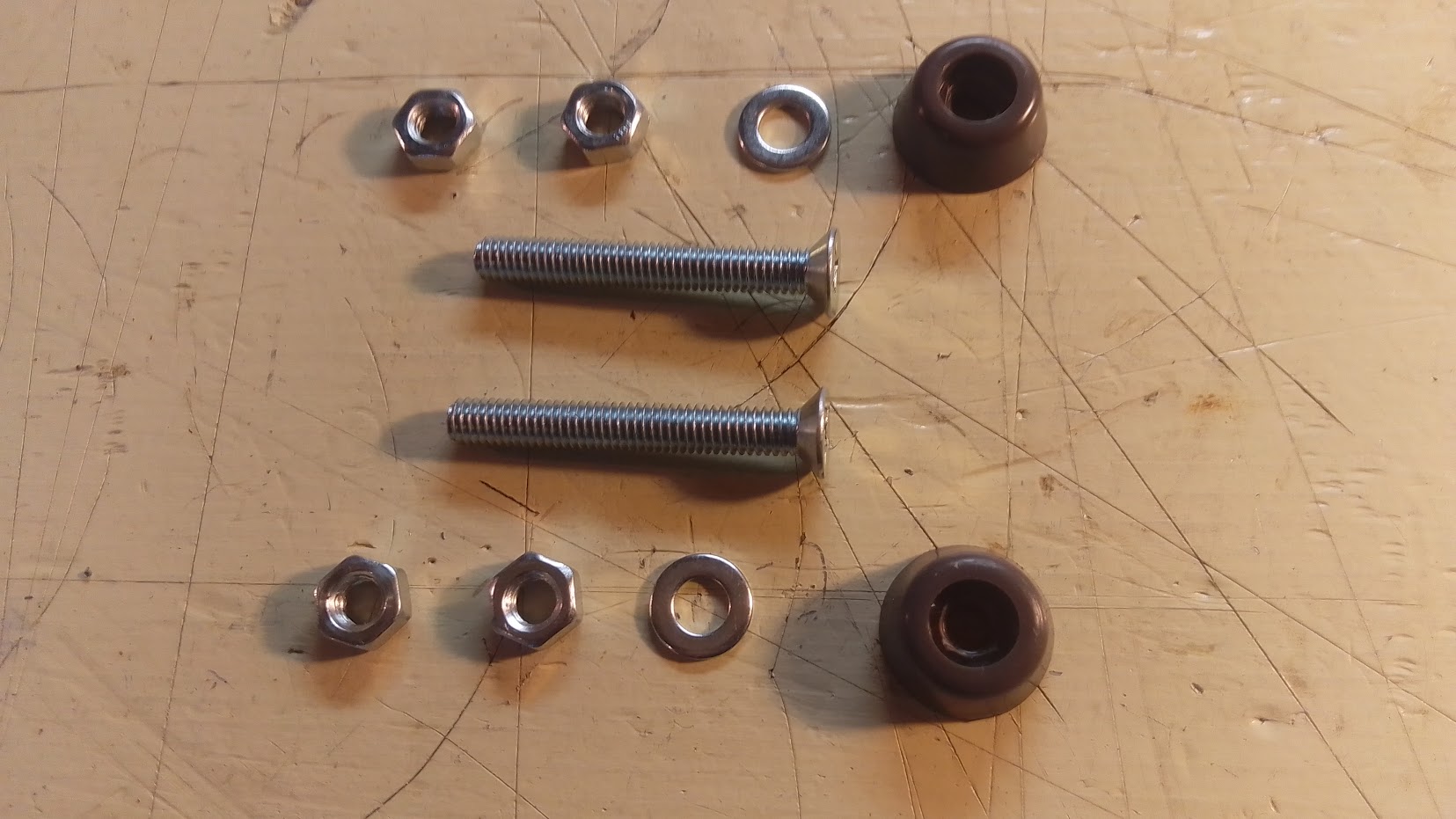
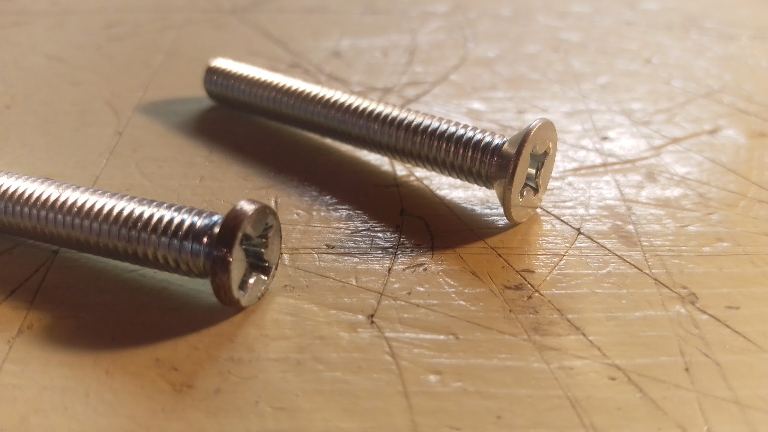
You will need some plastic pads like these I found at my local Ace Hardware. While I was there I grabbed a couple M6x1.0 45mm phillips head bolts with a tapered head. I had to grind down the head a little bit and drill and tap the hole of the plastic pad. Was rather easy. I also used a washer and a couple nuts to not only hold the plastic pad in place but to secure it to the headlight housing.


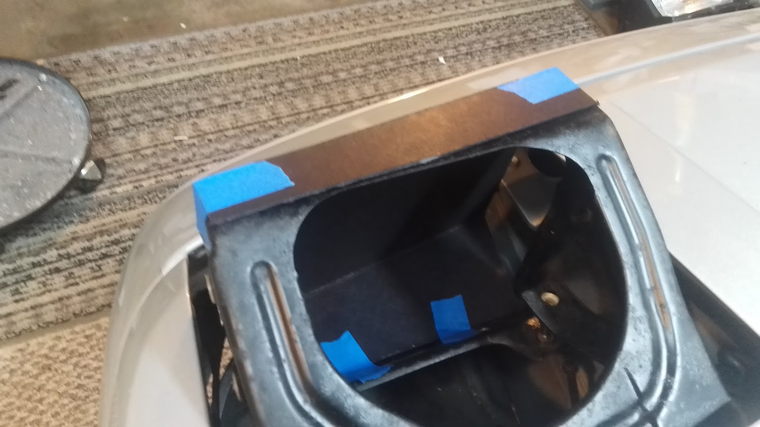
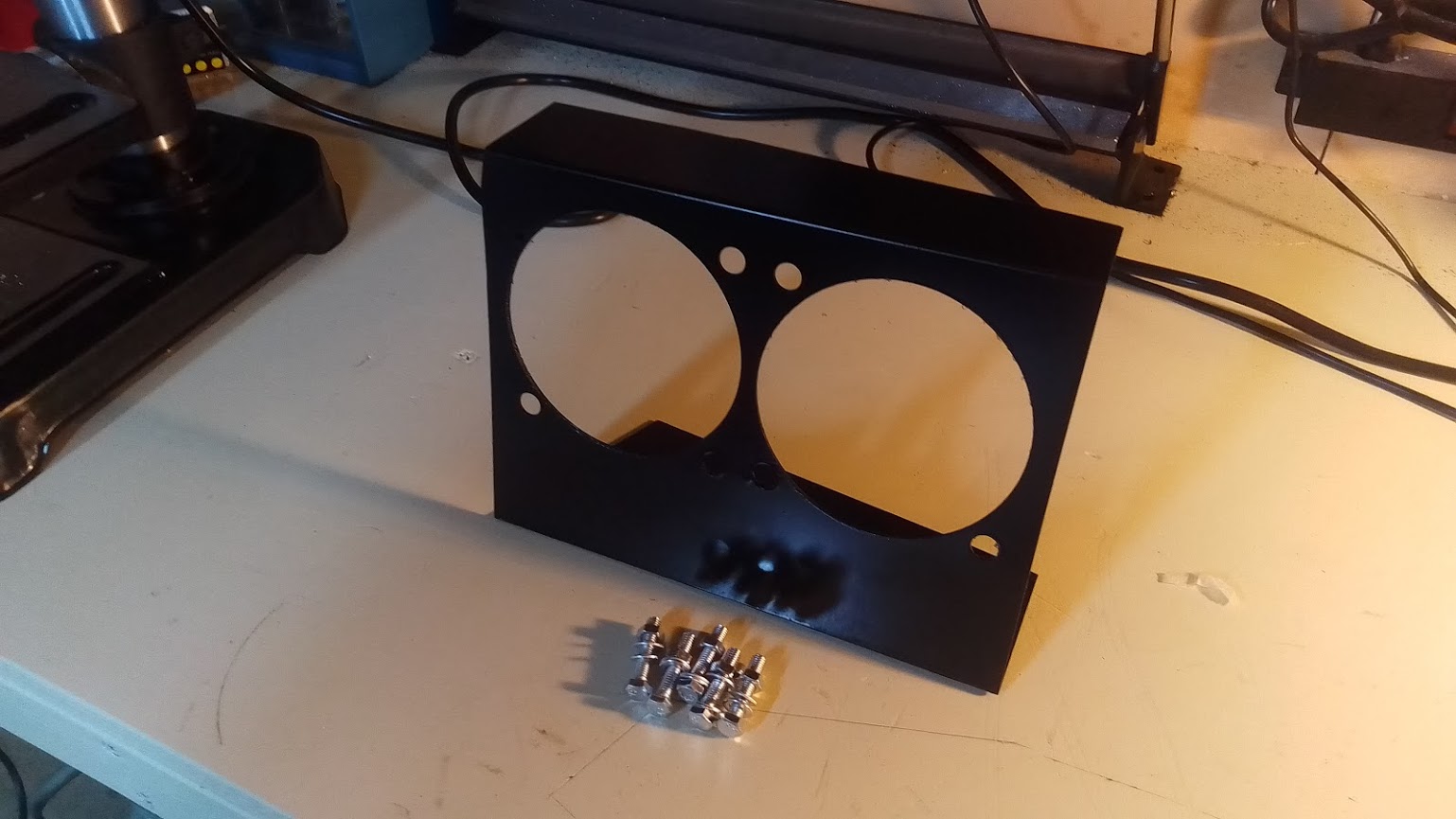
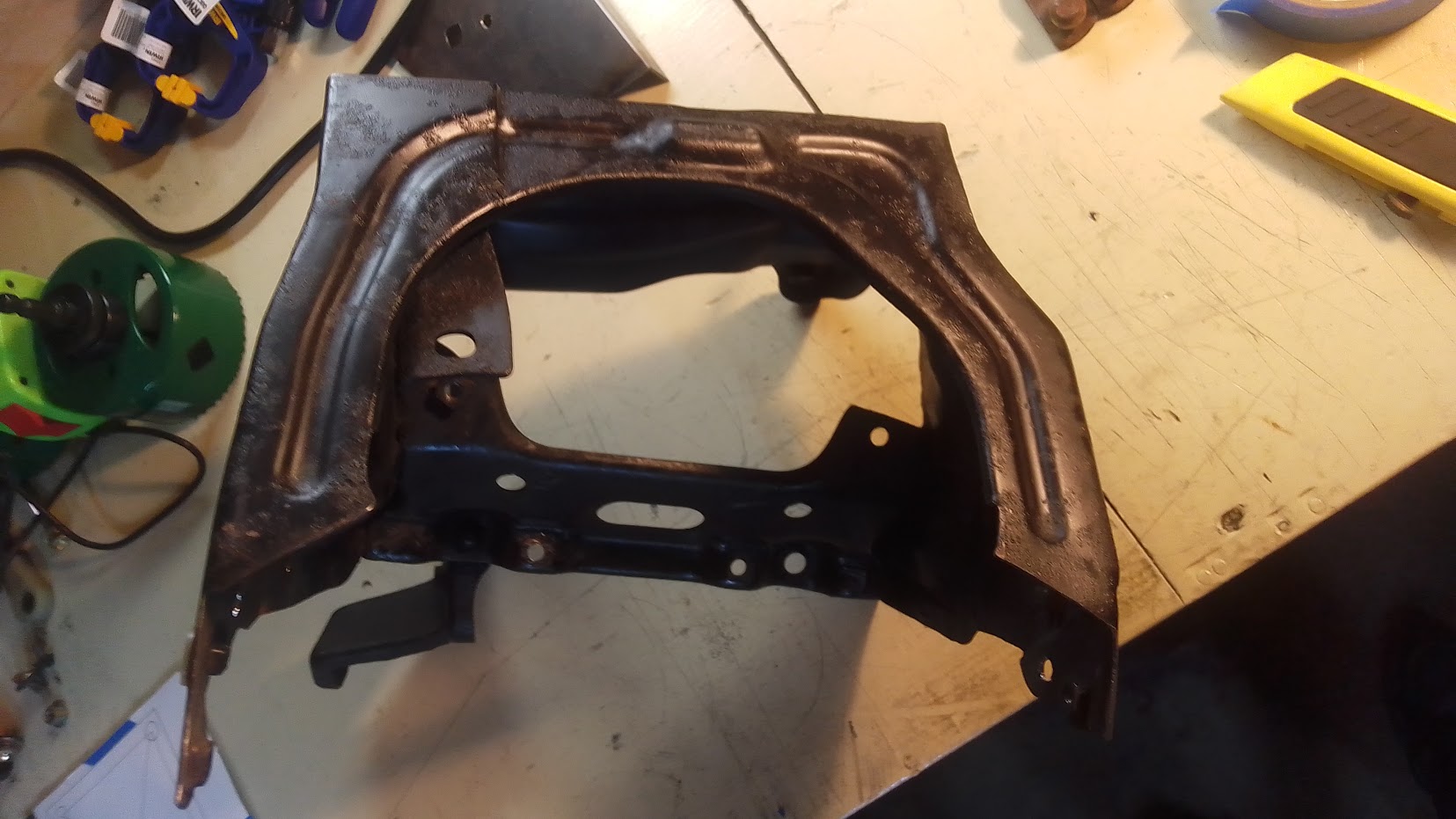
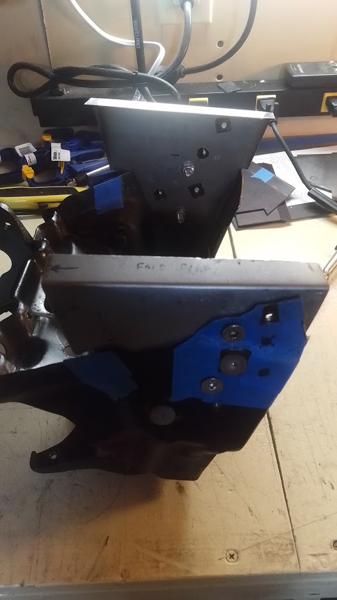
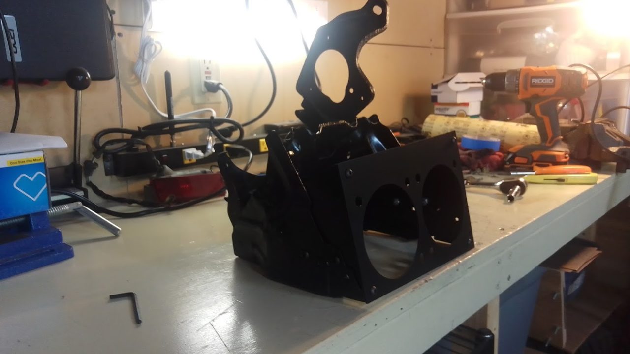
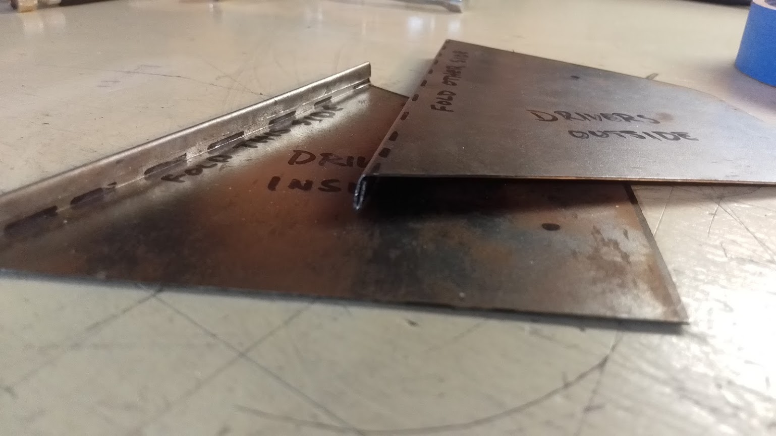
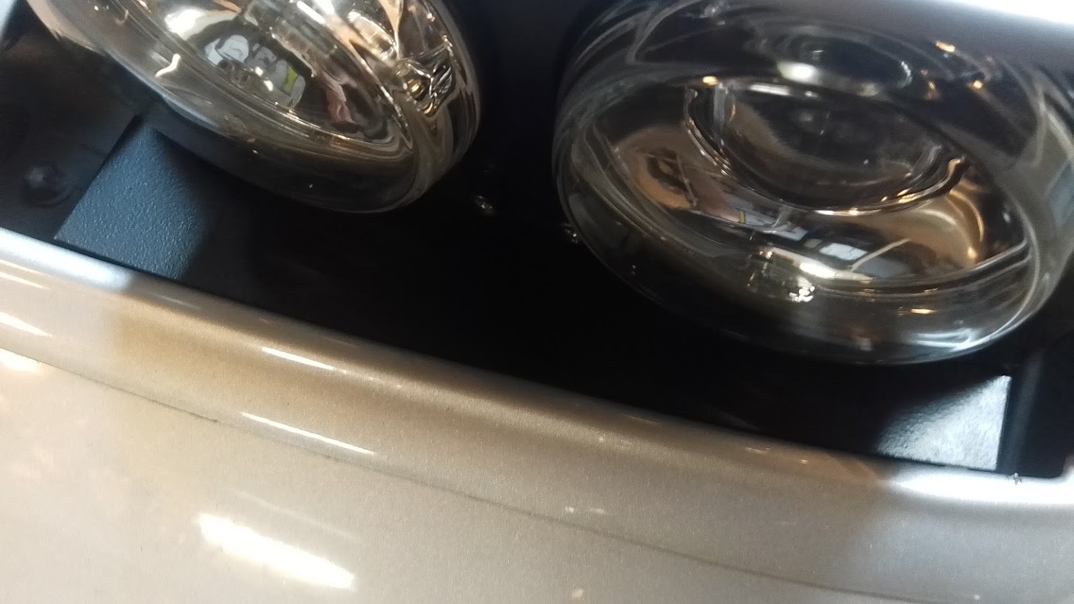
Next up I remade the design for how the Hella lights will attach to the housing. I had already removed the inner light bucket by grinding down the spot welds. I also cut out the top / front cross bar on the housings. This made room for the Hella’s to mount high enough. Not my best work and they will be painted.
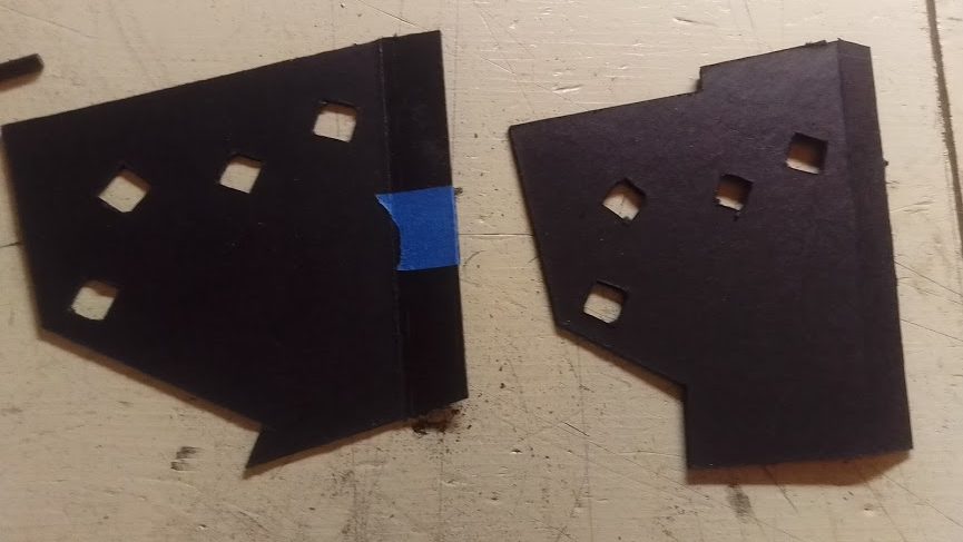
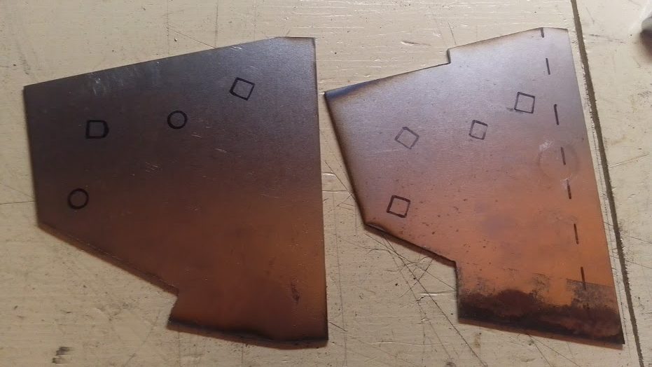

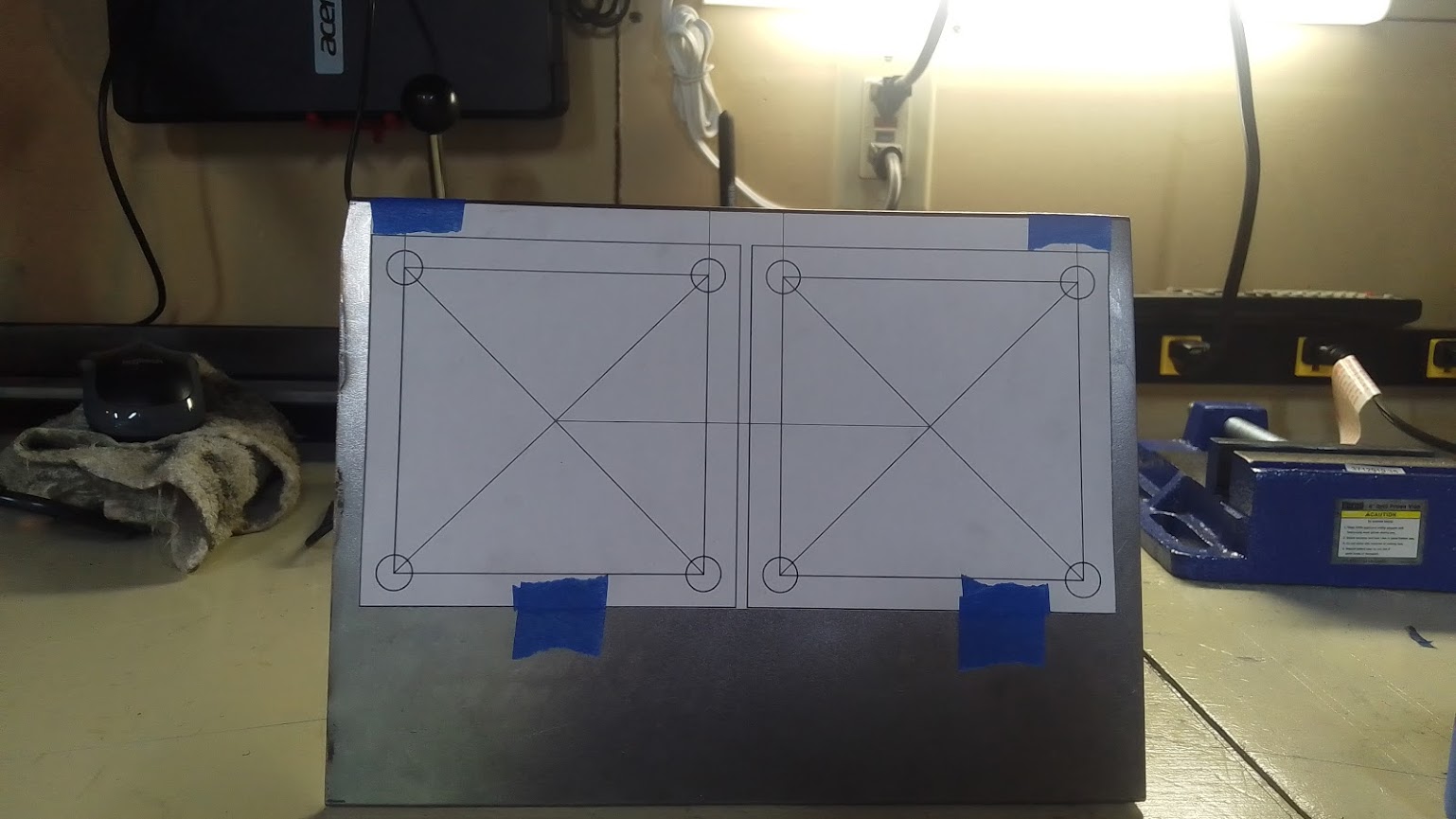
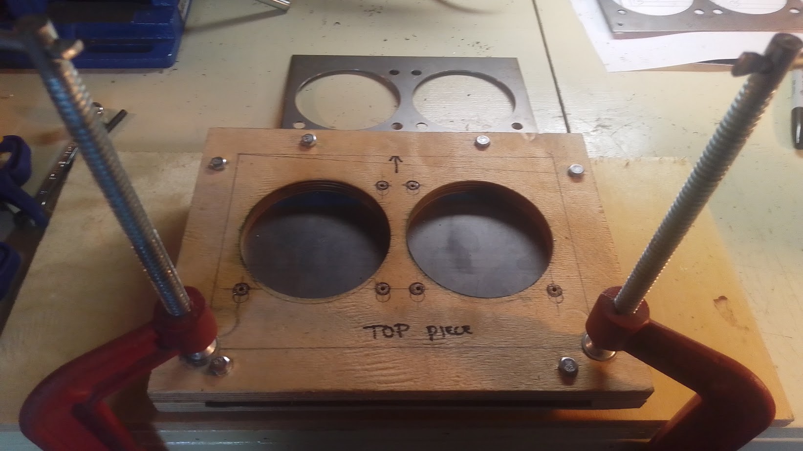
Ended up making a jig to hold the front plates in a specific position so all the holes lined up exactly the same and in the correct spots. Also helped a lot with the hole saw because even on the drill press the hole saw wanted to wander when it would start to bind.


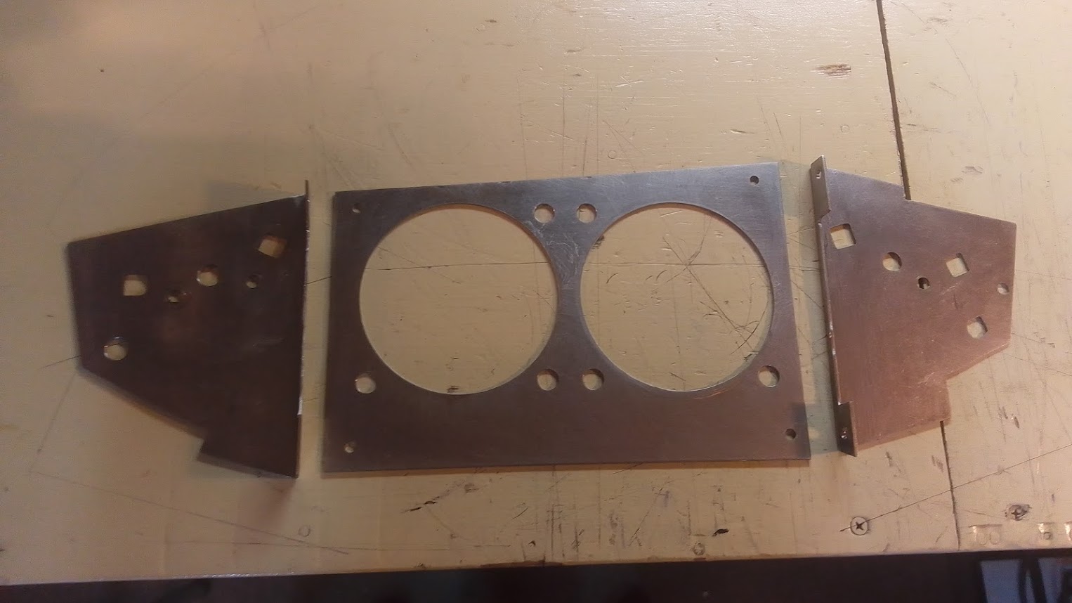
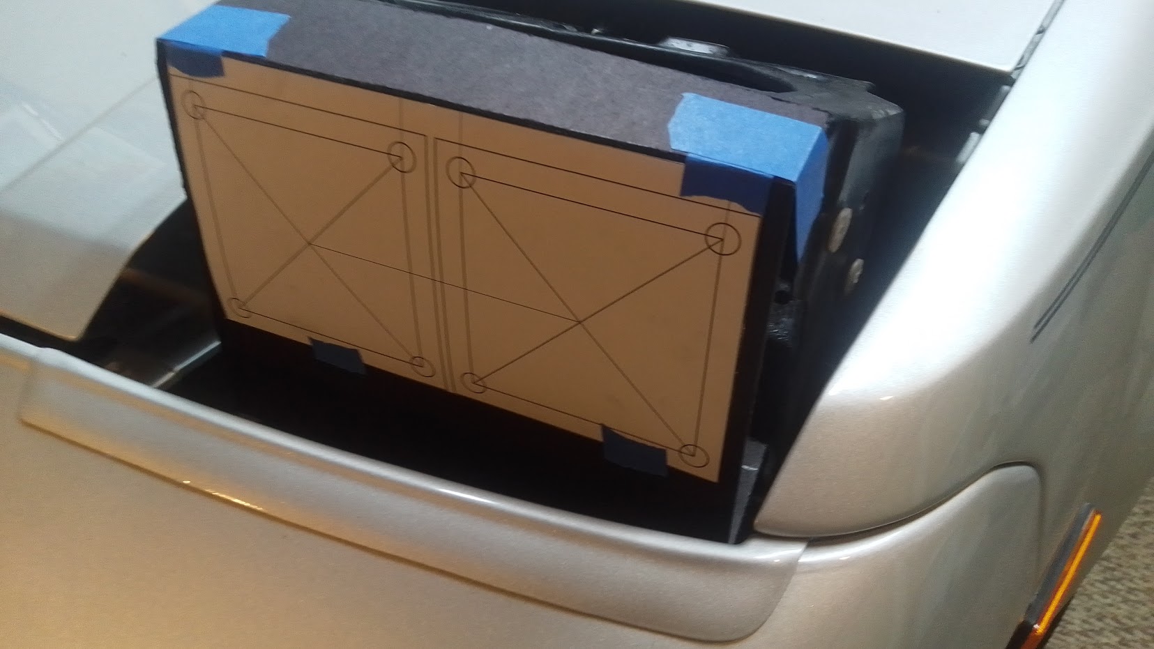
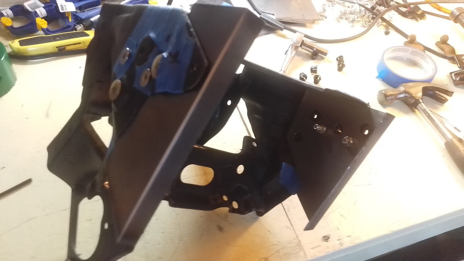
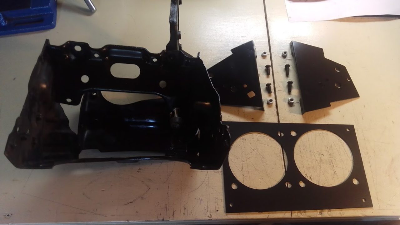
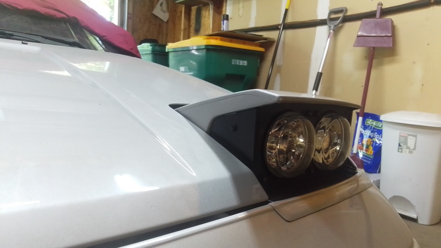
Here most of the pieces are painted and assembled so I can create the flat part that hides what’s behind the bumper area when the lights are up. This piece will attach to the bottom two mounting bolts that hold the front plate to the two side plates. This flat piece is also made out of 22 gauge steel instead of 16 gauge.


Here are some shots of what I created for the side covering pieces. Still pondering on the full bezel but these were simple enough to give them a fair try.

Also did some assembly after the paint had dried. Pro tip, assemble the Hella lights to the front plate while the front plate is attached to the side brackets. Do most of the assembly to the main headlight bucket outside of the car. Then attach the bucket with lights into the car, attach the motor, then the bump stop, and then the push rod. Once the push rod is in place, set the height on the bump stop. Then you can put the painted headlight cover on, adjust as needed to line it up with the fender and hood when the headlight is down, and then attach the side pieces or bezel if you went with a bezel design.
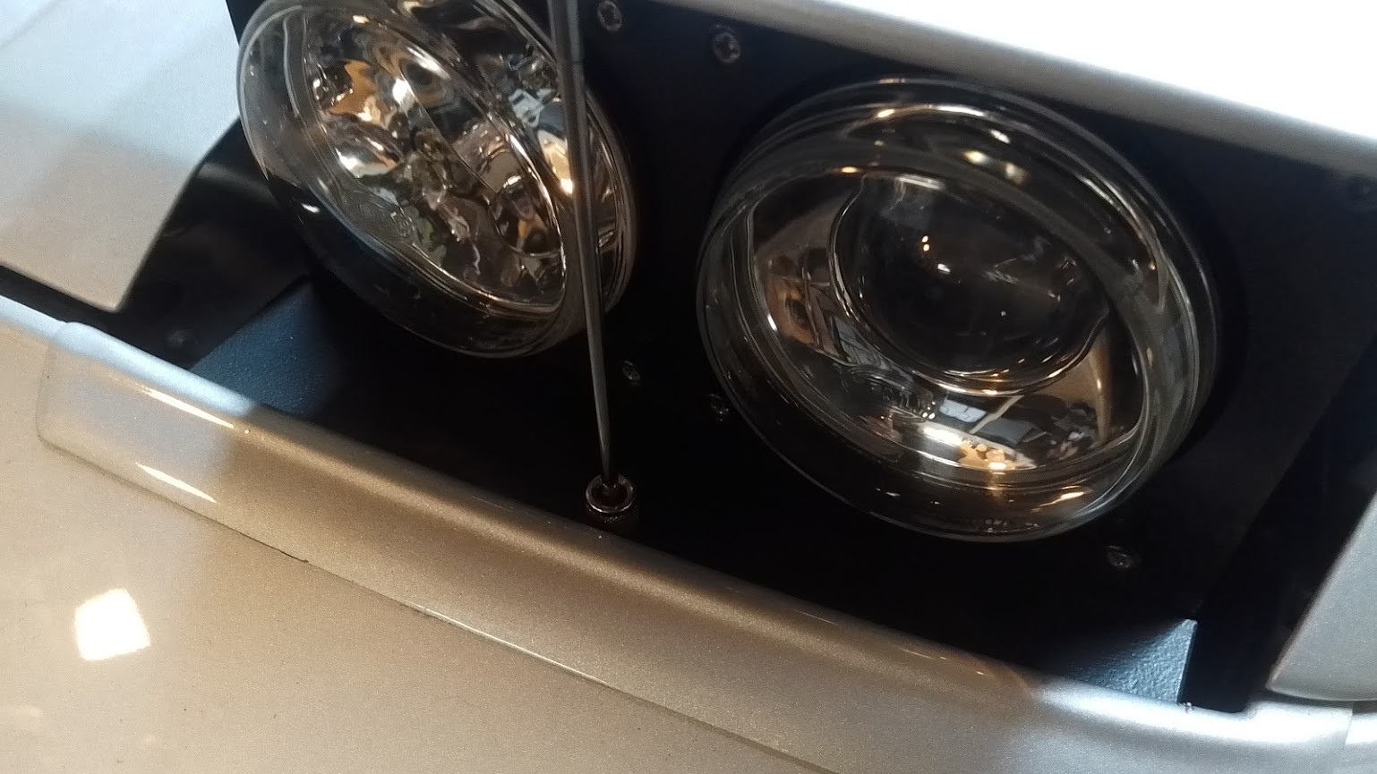
Here is the flat piece that hides the gap behind the bumper but in front of the lights. Since it’s painted black to match I set my magnet grabber tool on it so you can see it better.
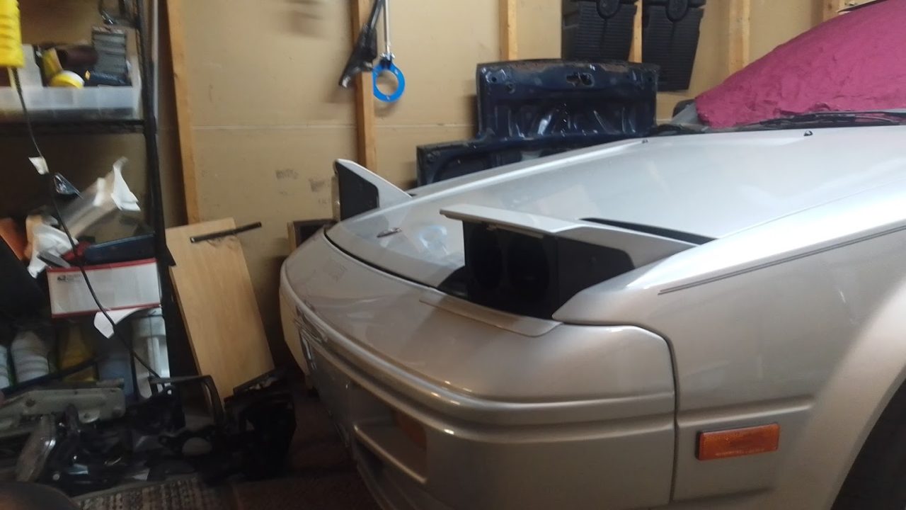
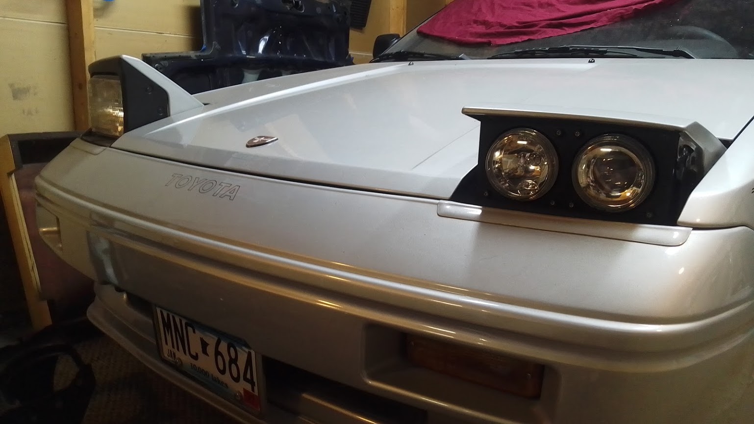
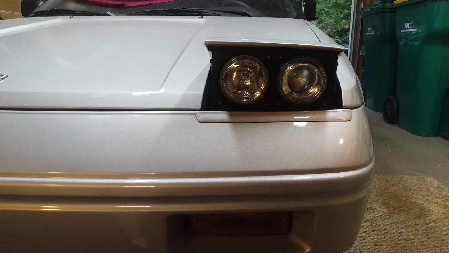
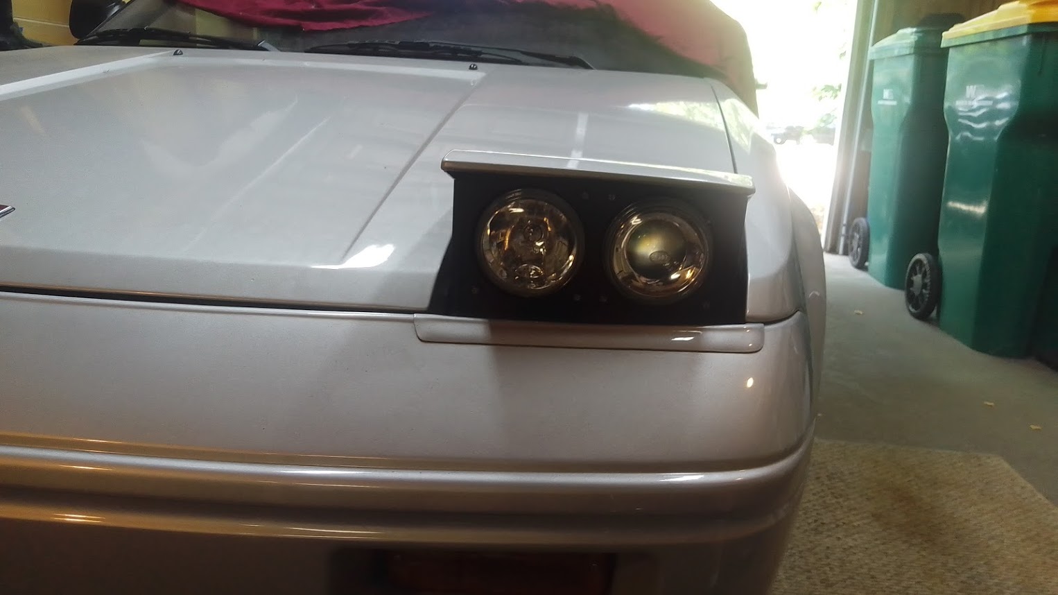
Here are some pictures with the side pieces finished up. I think I like it this way.


Here is a short video of things in action. Still need to put the side cover plates on but need to paint them first. Those are easy.
I hope this helps someone if they want to do the same thing or similar. I may also add information later if I forgot something or feel more detail is required. Keep in mind, this can be a DIY project but I hold no responsibility if you decide to do this to your car.